 |
nedoPC.orgElectronics hobbyists community established in 2002 |
 |
| Atom Feed | View unanswered posts | View active topics |
It is currently 04 Jun 2024 21:42 |
|
All times are UTC - 8 hours [ DST ] |
|
|
Page 1 of 1 |
[ 14 posts ] |
| Previous topic | Next topic |
DDT - free software for ternary circuits design
| Author | Message | |||||||||||||||||||||||||||
|---|---|---|---|---|---|---|---|---|---|---|---|---|---|---|---|---|---|---|---|---|---|---|---|---|---|---|---|---|
|
Admin  Joined: 08 Jan 2003 23:22 Posts: 22827 Location: Silicon Valley |
http://www.nedopc.org/ternary/ddt_0_4_win.zip (109K)
Currently DDT (Decision Diagrams for Ternary) source code is located on GitLab: https://gitlab.com/ternary/ddt Last edited by Shaos on 20 Sep 2012 20:10, edited 1 time in total. |
|||||||||||||||||||||||||||
| 01 Aug 2010 21:22 |
|
|||||||||||||||||||||||||||
|
Admin Joined: 08 Jan 2003 23:22 Posts: 22827 Location: Silicon Valley |
It is a free software covered by GPL v3, so source code is available on SourceForge:
http://nedopc.cvs.sourceforge.net/viewv ... c/src/ddt/ To get full sources of all NedoPC SDK do this: cvs -z3 -d:pserver:anonymous@nedopc.cvs.sourceforge.net:/cvsroot/nedopc checkout -P src |
|||||||||||||||||||||||||||
| 01 Aug 2010 21:24 |
|
|||||||||||||||||||||||||||
|
Admin Joined: 08 Jan 2003 23:22 Posts: 22827 Location: Silicon Valley |
Latest release for Windows:
http://www.nedopc.org/ternary/ddt_0_4_win.zip (109K) There is no visualization yet... |
|||||||||||||||||||||||||||
| 01 Aug 2010 21:25 |
|
|||||||||||||||||||||||||||
|
Admin Joined: 08 Jan 2003 23:22 Posts: 22827 Location: Silicon Valley |
Example of "reinvented" full ternary adder (SUM.ddt - i3,i2,i1=o2,o1):
ddtc SUM.ddt generates this c-source:
Testing results:
It requires 12 chips DG403 P.S. Interesting thing about this solution is that it's identical to the article from 1993: http://www.hindawi.com/journals/vlsi/19 ... 6.abs.html Actually DDT's automatic design made some improvements by changing 4 multiplexers to simpler devices (E12 and E21) - and because of that we need just 12 chips to implement 14 functions (each DG403 may be connected as two E12s or two E21s). |
|||||||||||||||||||||||||||
| 01 Aug 2010 21:35 |
|
|||||||||||||||||||||||||||
|
Retired
Joined: 03 Aug 2003 22:37 Posts: 1474 Location: Moscow |
Wow, at first reading I came to strange conclusion that you're talking about scheme that can dynamicaly rewire connections and so the processing device can read op-codes from RAM, decode it, rewire DG403s connections, execute the command and return result. That would be just fantastic - small ammount of executional set of DG403 chips (operational matrix) and large "re-wire controller". Crazy idea. I know I am crazy. |
|||||||||||||||||||||||||||
| 03 Aug 2010 04:31 |
|
|||||||||||||||||||||||||||
|
Admin Joined: 08 Jan 2003 23:22 Posts: 22827 Location: Silicon Valley |
No, DDT is for static solutions. Dynamic solution is also possible with DG403s, but it is heavy. 1-output ternary LUT (look-up table) based on DG403s requires D(n)=3*D(n-1)+1 chips, where n - number of inputs and D(1)=1, so: D(1)=1 (looks like ROM for 3 trits) D(2)=4 (looks like ROM for 9 trits) D(3)=13 (looks like ROM for 27 trits) D(4)=40 (looks like ROM for 81 trits) D(5)=121 (looks like ROM for 243 trits) D(6)=364 (looks like ROM for 729 trits) D(7)=1093 (looks like ROM for 2187 trits) D(8)=3280 (looks like ROM for 6561 trits) D(9)=9841 (looks like ROM for 19683 trits) D(10)=29524 (looks like ROM for 59049 trits) etc. Also if we have M outputs we need M*D(N) chips where N - number of inputs. Last edited by Shaos on 20 Sep 2012 20:10, edited 1 time in total. |
|||||||||||||||||||||||||||
| 04 Aug 2010 04:52 |
|
|||||||||||||||||||||||||||
|
Admin Joined: 08 Jan 2003 23:22 Posts: 22827 Location: Silicon Valley |
Now DDT generated these schemes:
NOT = 2 x DG403 (50% of them), MIN or MAX = 2 x DG403 (75% of them), Half Adder = 6 x DG403 (83% of them), Full Adder = 12 x DG403, Sign of 3-trit digit = 2 x DG403, Left/Right Shifter of 3-trit digit = 4 x DG403 (75% of them), Universal Unary Function for 3-trit argument = 4 x DG403 (75% of them), Universal Binary Function for 3-trit arguments = 12 x DG403, Converter 1-trit to 2-bit = 2 x DG403 (75% of them), Converter 2-trit to 4-bit = 8 x DG403, Converter 3-trit to 5-bit = 18 x DG403, Converter 4-trit to 7-bit = 39 x DG403, Converter 5-trit to 8-bit = 83 x DG403, Converter 6-trit to 10-bit = 162 x DG403, Converter 2-bit to 1-trit = 1 x DG403, Converter 4-bit to 2-trit = 11 x DG403, Converter 5-bit to 3-trit = 32 x DG403, Converter 7-bit to 4-trit = 80 x DG403, Converter 8-bit to 5-trit = 154 x DG403, Converter 10-bit to 6-trit = 309 x DG403 (not optimal), Increment/Decrement of 1-trit digit = 6 x DG403 (83% of them), Increment/Decrement of 2-trit digit = 10 x DG403, Increment/Decrement of 3-trit digit = 16 x DG403, Increment/Decrement of 4-trit digit = 22 x DG403, Increment/Decrement of 5-trit digit = 28 x DG403, Increment/Decrement of 6-trit digit = 34 x DG403, Increment/Decrement of 7-trit digit = 40 x DG403, Increment/Decrement of 8-trit digit = 46 x DG403, Increment/Decrement of 9-trit digit = 52 x DG403 (48 manually), Comparison 1-trit digits = 2 x DG403, Comparison 2-trit digits = 6 x DG403, Comparison 3-trit digits = 8 x DG403, Comparison 4-trit digits = 12 x DG403, Comparison 5-trit digits = 44 x DG403 (not optimal), Adder for 1-trit digits = 12 x DG403 (delay 3) - the same as Full Adder above, Adder for 2-trit digits = 28 x DG403 (delay 5) versus sequential version, created manually - 24 x DG403 with delay 6, Adder for 3-trit digits = 50 x DG403 (delay 7) versus sequential version, created manually - 36 x DG403 with delay 9, Adder for 4-trit digits = 76 x DG403 (delay 9) versus sequential version, created manually - 48 x DG403 with delay 12, Adder for 5-trit digits = 106 x DG403 (delay 11) versus sequential version, created manually - 60 x DG403 with delay 15, 1-trit Multiplier = 2 x DG403, 2-trit Multiplier = 30 x DG403, 3-trit Multiplier = 188 x DG403, 4-trit Multiplier = 1088 x DG403 |
|||||||||||||||||||||||||||
| 07 Dec 2010 05:04 |
|
|||||||||||||||||||||||||||
|
|
For addition, beyond 3 to 5 trits, you may need to look at higher level architecture such as carry-predict, or (my favorite) carry-select adders. The Select part of carry-select can be done with about 2/3 chip delays and about #trits/4 chips. (About because you are actually selecting not only the sum, but also the carry out).
|
|||||||||||||||||||||||||||
| 07 Dec 2010 06:14 |
|
|||||||||||||||||||||||||||
|
Admin Joined: 08 Jan 2003 23:22 Posts: 22827 Location: Silicon Valley |
Do you have a picture describing this approach? |
|||||||||||||||||||||||||||
| 07 Dec 2010 17:40 |
|
|||||||||||||||||||||||||||
|
|
http://en.wikipedia.org/wiki/Carry-select_adder has a good presentation for the binary case. For trinary obviously the select stages must choose between three 'speculativly' calculated sums: Ahi + Bhi + -1, Ahi + Bhi + 0, Ahi + Bhi + 1.
The chip count then is 3x(chips for multiply) + chips for 3:1 mux. And additional chips for adding the low part. Obvious extensions for more than two parts. Right now it is believed that the fastest adders that can be built use a carry predict portion and then a sum select portion. The "carry-select" adder is a hybrid, doing ripple carry between select stages. That is, if you are adding Alo Amed Ahi to Blo Bmed Bhi, then which of the three computations of Bhi + Ahi + C depends on the result of which of the choices of Bmed + Amed you made. The pictures make it much clearer I think. Jay |
|||||||||||||||||||||||||||
| 07 Dec 2010 19:05 |
|
|||||||||||||||||||||||||||
|
Admin Joined: 08 Jan 2003 23:22 Posts: 22827 Location: Silicon Valley |
I just finished some visualization for full adder:
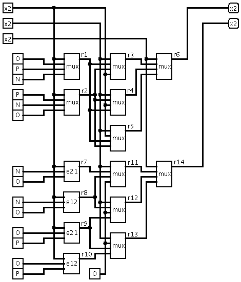
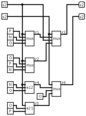
Schematics were created in Logisim - "x2" means "ternary input/output" P.S. Image creation is not yet automatic... |
|||||||||||||||||||||||||||
| 02 Jan 2011 20:43 |
|
|||||||||||||||||||||||||||
|
Admin Joined: 08 Jan 2003 23:22 Posts: 22827 Location: Silicon Valley |
1-trit half-adder (or 1-trit increment/decrement scheme):
Manually created 3-trit increment/decrement scheme (3 half-adders are used): 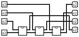 |
|||||||||||||||||||||||||||
| 07 Jan 2011 07:50 |
|
|||||||||||||||||||||||||||
|
Admin Joined: 08 Jan 2003 23:22 Posts: 22827 Location: Silicon Valley |
Interesting, but I just found DDT approach described in the book from 1975: S.Thelliez "Introduction to the study of ternary switching structures (Information and systems theory, Volume 4)". In this book ternary multiplexer named "T operator".
|
|||||||||||||||||||||||||||
| 10 Aug 2011 20:48 |
|
|||||||||||||||||||||||||||
|
Admin Joined: 08 Jan 2003 23:22 Posts: 22827 Location: Silicon Valley |
currently working on visualization...
|
|||||||||||||||||||||||||||
| 10 Nov 2012 09:04 |
|
|||||||||||||||||||||||||||
|
|
Page 1 of 1 |
[ 14 posts ] |
|
All times are UTC - 8 hours [ DST ] |
Who is online |
Users browsing this forum: No registered users and 1 guest |
| You cannot post new topics in this forum You cannot reply to topics in this forum You cannot edit your posts in this forum You cannot delete your posts in this forum You cannot post attachments in this forum |