 |
nedoPC.orgElectronics hobbyists community established in 2002 |
 |
| Atom Feed | View unanswered posts | View active topics |
It is currently 25 Apr 2024 20:38 |
|
All times are UTC - 8 hours [ DST ] |
Ternary testing board TRInnTest-1
Moderator: haqreu
|
|
Page 1 of 1 |
[ 3 posts ] |
| Previous topic | Next topic |
Ternary testing board TRInnTest-1
| Author | Message |
|---|---|
|
Admin  Joined: 08 Jan 2003 23:22 Posts: 22586 Location: Silicon Valley |
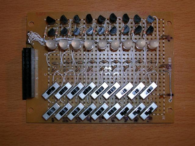
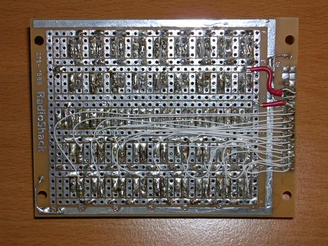
On June 13rd 2005 I finished 5-day building of ternary testing board to test our "standard" ternary elements with 12 and 24 pins:
  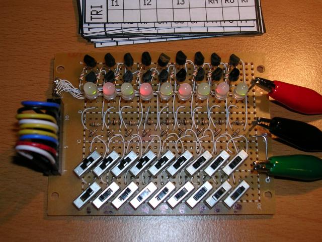 This is testing of TRI31 double ternary half adder:  P.S. Russain topic about this board: viewtopic.php?t=51 |
| 31 Aug 2008 16:56 |
|
|
Admin Joined: 08 Jan 2003 23:22 Posts: 22586 Location: Silicon Valley |
Board uses 18 "ternary" mechanical switches, 9 "ternary" red-green LEDs, 27 resistors and 18 bipolar transistors (9 PNP and 9 NPN). Scheme consists of 9 identical blocks:
Lower 9 pins of TRInn elements may be inputs or outputs ("IO" on the scheme). Higher 9 pins are usually inputs ("I" on the scheme). Improper usage of that board may cause short circuit of power supply - if ternary switch wrongly will connect +5V or -5V to output pin when tested board will provide -5V or +5V to the same output. So all switches that connected to outputs MUST be in neutral position! As defense against this condition we can put additional 1K resistor before every IO. |
| 31 Aug 2008 16:57 |
|
|
Admin Joined: 08 Jan 2003 23:22 Posts: 22586 Location: Silicon Valley |
up
|
| 10 Nov 2012 07:16 |
|
|
|
Page 1 of 1 |
[ 3 posts ] |
|
All times are UTC - 8 hours [ DST ] |
Who is online |
Users browsing this forum: No registered users and 5 guests |
| You cannot post new topics in this forum You cannot reply to topics in this forum You cannot edit your posts in this forum You cannot delete your posts in this forum You cannot post attachments in this forum |