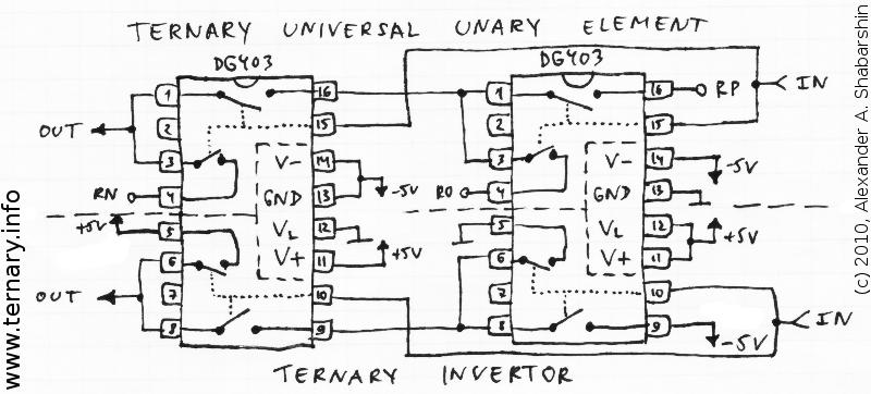
Schematics are very simple:
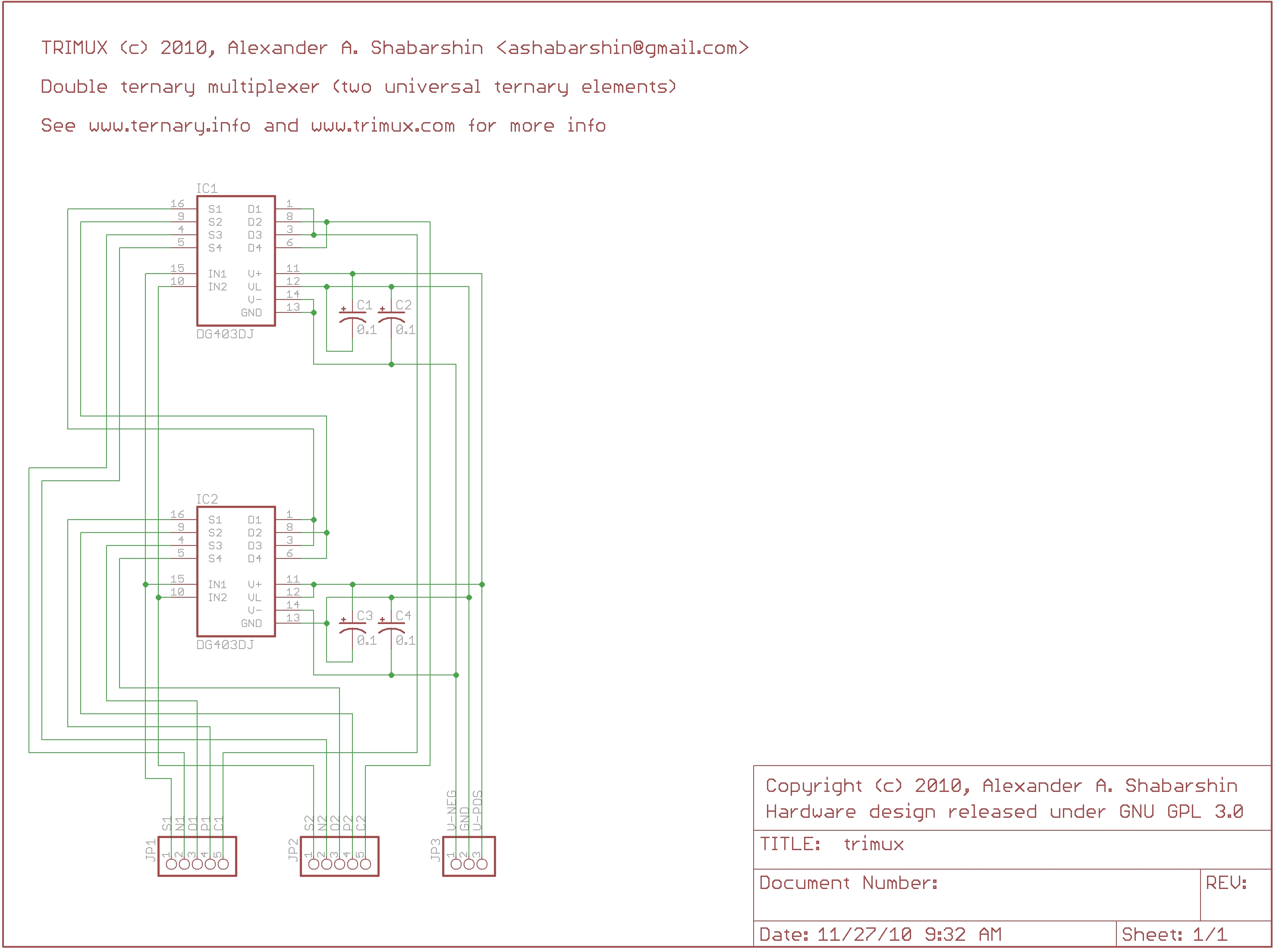
IC1,IC2: DG403 (DIP16)
C1,C2,C3,C4: 0.1uF (tantalum)
JP1,JP2: right-angle 5-pin headers
JP3: right-angle 3-pin header
Connector JP1:
1) S1 - select input of the 1st ternary multiplexer
2) N1 - connected to C1 (common signal of the 1st ternary multiplexer) if S1=N ("negative" or -5V)
3) O1 - connected to C1 (common signal of the 1st ternary multiplexer) if S1=O ("zero" or 0V)
4) P1 - connected to C1 (common signal of the 1st ternary multiplexer) if S1=P ("positive" or +5V)
5) C1 - common signal of the 1st ternary multiplexer
Connector JP2:
1) S2 - select input of the 2nd ternary multiplexer
2) N2 - connected to C2 (common signal of the 2nd ternary multiplexer) if S2=N ("negative" or -5V)
3) O2 - connected to C2 (common signal of the 2nd ternary multiplexer) if S2=O ("zero" or 0V)
4) P2 - connected to C2 (common signal of the 2nd ternary multiplexer) if S2=P ("positive" or +5V)
5) C2 - common signal of the 2nd ternary multiplexer
Connector JP3:
1) V-NEG - negative voltage (typically -5V)
2) GND - ground wire
3) V-POS - positive voltage (typically +5V)
P.S. Eagle design released under GPL v3: http://www.nedopc.org/ternary/trimux-eagle.zip (296K)
P.P.S. Also I developed software package for automatic design of ternary schemes based on DG403:
viewtopic.php?t=172
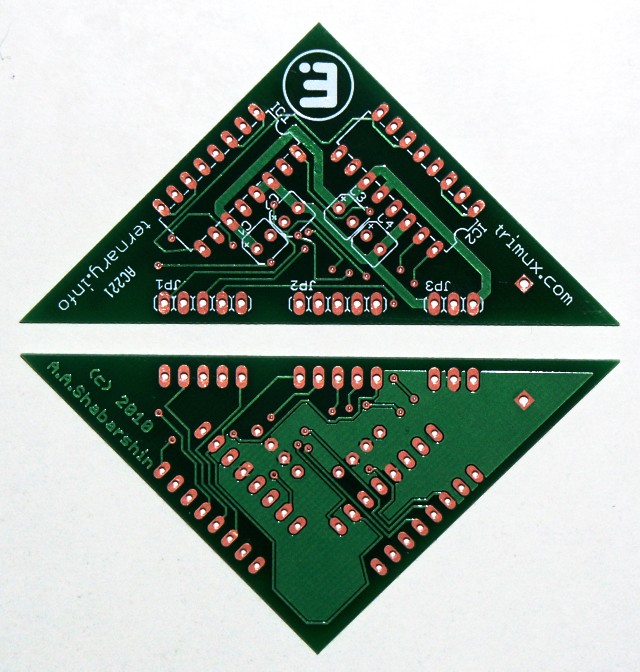
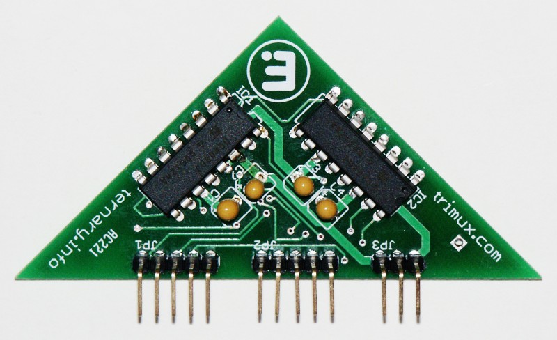
P.P.P.S. Assembled TRIMUX:
Components: http://www.mouser.com/ProjectManager/Pr ... 38f4dfdfd8
Since 2015 it's availabe for purchase from Tindie marketplace:
https://www.tindie.com/products/TRC/tri ... ltiplexer/