Ternary testing board TRInnTest-1

Balanced Ternary Numeral System - forum was moved from http://ternary.info

Moderator: haqreu

User avatar
Shaos
Admin
Posts: 23989
Joined: 08 Jan 2003 23:22
Location: Silicon Valley

Ternary testing board TRInnTest-1

Post by Shaos »

On June 13rd 2005 I finished 5-day building of ternary testing board to test our "standard" ternary elements with 12 and 24 pins:

Image

Image

Image

This is testing of TRI31 double ternary half adder:

Image

P.S. Russain topic about this board: viewtopic.php?t=51
User avatar
Shaos
Admin
Posts: 23989
Joined: 08 Jan 2003 23:22
Location: Silicon Valley

Re: Ternary testing board TRInnTest-1

Post by Shaos »

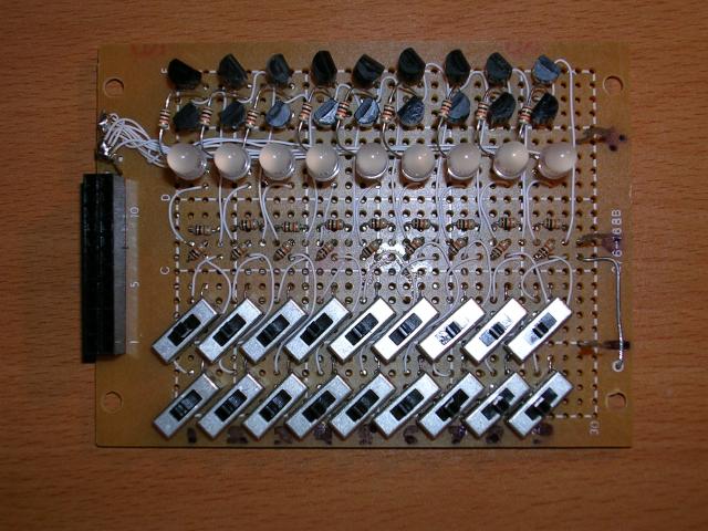
Board uses 18 "ternary" mechanical switches, 9 "ternary" red-green LEDs, 27 resistors and 18 bipolar transistors (9 PNP and 9 NPN). Scheme consists of 9 identical blocks:

Image

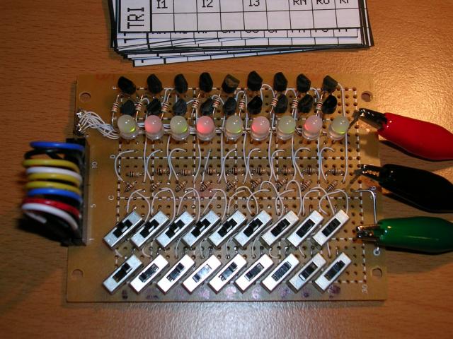
Lower 9 pins of TRInn elements may be inputs or outputs ("IO" on the scheme). Higher 9 pins are usually inputs ("I" on the scheme). Improper usage of that board may cause short circuit of power supply - if ternary switch wrongly will connect +5V or -5V to output pin when tested board will provide -5V or +5V to the same output. So all switches that connected to outputs MUST be in neutral position! As defense against this condition we can put additional 1K resistor before every IO.
User avatar
Shaos
Admin
Posts: 23989
Joined: 08 Jan 2003 23:22
Location: Silicon Valley

Post by Shaos »

up
Я тут за главного - если что шлите мыло на me собака shaos точка net